Posts

Showing posts from March, 2024

Introduction(Sensors)

Image
 What is a Sensor? A sensor is a device that detects physical or environmental changes, including speed, pressure, temperature, light, heat, humidity, and more. Similar to our human senses like eyes, ears, and nose that collect information and send it to the brain, electronic sensors detect and transmit data to a processor or microcontroller. Types of Sensors: This section will explore some common types of sensors: Proximity Sensor: Detects the presence or proximity of an object within a certain range. It can utilize sound, light, infrared radiation, or electromagnetic fields depending on its specific type. Light Sensor: Detects light intensity and adjusts device features accordingly, such as automatically adjusting phone screen brightness based on ambient light. Accelerometer: Detects device orientation (portrait or landscape) and can be used for various functionalities like rotating the screen automatically. It typically functions within a 90-degree range. Ultrasonic Sensor: Meas

Basic Component (Embedded System)

 Basic Components for Electronics Projects This chapter introduces some fundamental components commonly used in electronics projects. These components include: Seven Segment Display  Servo Motor LMIC Keypad Regulator IC Bluetooth Module Hc05 Buzzer Humidity / Temp Sensor Seven-Segment Display: This is a display device that can display decimal numbers and is often used in digital clocks, meters, calculators, and other electronic devices. It consists of seven individual LEDs arranged in a specific configuration to form various numbers and symbols. Working Principle: Each LED in a seven-segment display is assigned a number (as shown in the image). To display a specific digit, certain LEDs are turned on (active mode) while others are turned off. Example: To display the number 5, LEDs E, F, G, C, and D would be turned on, creating the shape of a "5." Similarly, any numerical digit can be displayed by selectively activating the corresponding LEDs. By combining multiple seven-segm

Arduino

Image
Arduino Arduino is an open-source electronics platform widely used for creating electronic projects. It's essentially a hardware module with a built-in microcontroller chip, programmed using software. There are various Arduino boards available, with the Arduino Uno being a popular choice. We'll explore building projects using this board later in the course. Origin of Arduino Arduino originated at the Interaction Design Institute Ivrea in Italy. Its purpose was to facilitate a better learning experience for students in electronics, particularly for children. Additionally, Arduino IDE, a free software platform, serves as the primary tool for programming Arduino boards. Different Arduino Boards Several Arduino boards cater to diverse project needs. We'll delve deeper into specific models in the following sections. The Arduino Uno is a microcontroller board equipped with: 14 digital input/output pins for connecting various devices 6 analog input pins for reading analog data 16

Programming

Image
 Programming A program is a collection of instructions that dictate the behavior of a computer. The CPU processes these instructions, resulting in the desired output. These instructions are written in a specific language known as a programming language. In this chapter, we'll focus on how these languages are used in embedded systems. Later, we'll explore specific programming languages used in this field. Since embedded systems are designed for specific tasks, microcontrollers need to be programmed with instructions relevant to those tasks. For example, a washing machine has a program that controls the motor's rotation (clockwise and anti-clockwise) upon turning it on. Hands-on Learning: To gain a deeper understanding of programming and embedded systems, creating your own project is highly recommended. You can work with a microcontroller module and program it to control a motor's rotation in both directions (clockwise and anti-clockwise). We'll provide further projec

Microcontrollers

Image
 Microcontrollers A microcontroller is a digital computer on a single chip, integrating a microprocessor, memory, and input/output (I/O) devices. Unlike a general-purpose computer, a microcontroller is designed to perform specific tasks like light sensing and device control. Once programmed, it executes these tasks autonomously. Another way to understand a microcontroller is as a type of microcomputer that combines various components on a single chip, including: Input/Output (I/O) ports: for communication with external devices Timers and counters: for timing and control functions Memory: for storing program instructions and data Analog-to-Digital (A/D) converter: for converting analog signals to digital Digital-to-Analog (D/A) converter: for converting digital signals to analog Learning Through Practice: To gain a deeper understanding of microcontrollers, creating a project and programming it to perform various tasks is highly recommended. Popular Microcontroller Modules: Several

Microprocessors

 Microprocessors Initially, computers were built using individual logic gates. This stage is called Small-Scale Integration (SSI). As technology advanced, Medium-Scale Integration (MSI) and Super Large-Scale Integration (SLSI) were developed, allowing the entire CPU to be integrated onto a single chip. This chip, also known as a microprocessor, forms the core of a microcomputer. Today, microprocessors are present in various devices, including computers, smartphones, and tablets. The block diagram above illustrates the basic operation of a CPU. It receives instructions from memory, processes data accordingly, and displays or transmits the result to an output device following the program's instructions. Example: When you enter an instruction like "2 + 2" into the calculator application, the input device transmits this instruction to the CPU. The CPU then processes it and displays the corresponding result (4) on the output device (monitor) or stores it in memory. Main Compon

Introduction

Image
Introduction An embedded system is designed to perform a specific task. The term "embedded" refers to its integration within a larger system, while "system" signifies its structured nature. The three main components of an embedded system are hardware, software, and Real-Time Operating System (RTOS). Let's delve into these components with an example. Example: Streetlight Automation We all encounter streetlights that turn on at dusk and off at dawn. This functionality is achieved by a simple embedded system. By combining an LED, a power source, and programming within an electronic device, the system operates according to the embedded instructions. We will explore practical applications of embedded systems later, but first, let's understand their basic components. Embedded Systems: A Historical Note Charles Stark Draper at the MIT Instrumentation Center is credited with developing embedded systems. Main Components of an Embedded System Hardware: Microcontroller

Transistor Testing

Image
Transistor Testing  Transistor Testing in Continuity Mode: A transistor has three terminals: base, emitter, and collector. To test them using the continuity mode of your multimeter, follow these steps: (1) Set the multimeter to continuity mode. (2) Place either the black or red probe on the base of the transistor. (3) Touch the other probe sequentially on the emitter and collector. (4) If both readings are the same, the transistor is good. (5) If there is no reading in the initial configuration, switch the base       probe and repeat steps 2 and 3. One of these combinations should       now show a reading, indicating a good transistor. Identifying Transistor Type: To determine whether the transistor is NPN or PNP, pay attention to which configuration results in a reading and which probe is on the base in that configuration: If the red probe is on the base when a reading appears, the transistor is PNP. If the black probe is on the base when a reading appears, the transistor is NPN.

Diode Testing

Image
 Diode Testing If the red probe (positive) of the multimeter is connected to the anode (positive) of the diode, and the black probe (negative) is connected to the cathode (negative) of the diode, a forward voltage reading will be displayed on the multimeter. When the probes are reversed, there should be no reading. This indicates a good diode. If the multimeter displays a reading in both forward and reverse bias conditions (when the probes are swapped), the diode is faulty.

Capacitor Testing

Image
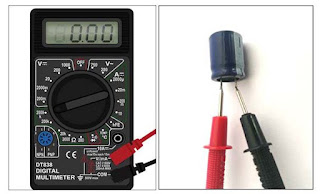
 Capacitor Testing Before checking a capacitor, ensure it is discharged. If not, discharge it safely. You can check the capacitor using a digital multimeter in both resistance and continuity modes. This guide will focus on the continuity mode method. Steps: Identify the capacitor type: Determine if it is a polar or non-polar capacitor. Non-polar capacitor: Connect the multimeter probes to the capacitor's terminals. If a beep sounds, the capacitor is faulty (short circuit). No beep indicates a good capacitor. Polar capacitor: Briefly touch the probes to the terminals . You may see a brief reading, followed by a value of 1. This indicates a good capacitor. You may also reverse the probes and repeat the process for confirmation. Note: Discharging capacitors requires caution and specific methods. Always consult a professional or relevant resources for safe discharging procedures.

Resistor Testing

Image
Resistor Testing  Resistors are a common component used in electronic circuits, but when building a circuit, it is important to pay attention to whether its value is correct or faulty. You can also find its value through color coding, or some have their values marked on them. Let's learn how to find the value of any resistor and whether it is okay or faulty. Here are the steps on how to check the value of a resistor: Check the color code. Resistors are color-coded, which means that the value of the resistor is indicated by the colors of the bands on its body. The first two bands represent the first two digits of the resistor's value, the third band represents the multiplier, and the fourth band represents the tolerance. For example, a resistor with the following color bands: Brown (1) Black (0) Red (2) Gold (5%) Would have a value of 100 ohms with a tolerance of 5 %. Use a multimeter. Step 1 First, set the black probe of the multimeter to Common Mode and the red probe to R

Introduction

 An Introduction to Components Testing Welcome to the exciting world of electronics! As you embark on your journey, understanding how to test and verify the functionality of various electronic components is crucial. These components testing forms a vital foundation for successful circuit building and troubleshooting. Why is Components Testing Important? Imagine building a complex structure with faulty bricks. The entire structure would be compromised, right? Similarly, using faulty components can lead to malfunctioning circuits, wasted time, and frustration. By testing components beforehand, you can avoid these pitfalls and ensure your circuits perform as intended. The Tools of the Trade: Just like any other profession, electronics has its own set of specialized tools. Here are some key instruments for component testing: Multimeter: This versatile tool measures voltage, current, and resistance, allowing you to check the basic health of various components like resistors, capacitors, an

Digital Multimeter

Image
Digital Multimeter A digital multimeter is an electronic instrument used to measure the values of various electrical quantities, such as resistance, capacitance, and voltage. It can be used for both DC and AC. The multimeter has different sections for measuring each quantity, which can be set using the rotary knob. It also has a display to show the measured value. Two probes are provided to make contact with a component or PCB. Key Points A digital multimeter is an electronic instrument used to measure electrical quantities. It can measure resistance, capacitance, and voltage. It can be used for both DC and AC. It has different sections for measuring each quantity. It has a rotary knob to set the measurement mode. It has a display to show the measured value. It has two probes to make contact with a component or PCB.

Transformer

Image
Transformer A transformer is a static device that transfers electrical energy from one circuit to another circuit, either increasing or reducing the voltage while keeping the frequency the same. It works on the principle of electromagnetic induction. If it converts a low voltage level to a high voltage level, it is called a step-up transformer. If it converts a high voltage level to a low voltage level, it is called a step-down transformer. There are many types of transformers. In this chapter, we will mainly discuss small transformers that are used in electronic circuits , also known as electronic transformers. Structure: A transformer has two coils, called the primary winding and the secondary winding. It also has a core on which the coils are wound. The coils are electrically isolated but magnetically coupled. The core can be either core-type or shell-type . Types of Small Transformers There are two main types of small transformers: Core-type Shell-type Working: When an AC voltage

Diode

Image
 Diode The world of electronics is built upon the foundation of various components, each playing a crucial role in directing the flow of electricity. Among these essential players, the humble diode stands out for its simplicity and versatility. In this blog post, we'll delve into the fascinating realm of diodes, exploring their core principles, functionalities, and diverse applications in basic electronics. Introduction: A diode, in its essence, is a two-terminal electronic component that acts like a one-way street for electricity. This means it readily allows current to flow in one direction (forward bias) but significantly restricts it in the opposite direction (reverse bias). Imagine it as a gatekeeper, meticulously controlling the movement of electrical charges. How Does a Diode Function? The secret behind the diode's directional control lies in its unique internal structure. It's crafted from a special material called a semiconductor, typically silicon, and is further