Posts

Introduction

Image
Introduction An embedded system is designed to perform a specific task. The term "embedded" refers to its integration within a larger system, while "system" signifies its structured nature. The three main components of an embedded system are hardware, software, and Real-Time Operating System (RTOS). Let's delve into these components with an example. Example: Streetlight Automation We all encounter streetlights that turn on at dusk and off at dawn. This functionality is achieved by a simple embedded system. By combining an LED, a power source, and programming within an electronic device, the system operates according to the embedded instructions. We will explore practical applications of embedded systems later, but first, let's understand their basic components. Embedded Systems: A Historical Note Charles Stark Draper at the MIT Instrumentation Center is credited with developing embedded systems. Main Components of an Embedded System Hardware: Microcontroller...

Transistor Testing

Image
Transistor Testing  Transistor Testing in Continuity Mode: A transistor has three terminals: base, emitter, and collector. To test them using the continuity mode of your multimeter, follow these steps: (1) Set the multimeter to continuity mode. (2) Place either the black or red probe on the base of the transistor. (3) Touch the other probe sequentially on the emitter and collector. (4) If both readings are the same, the transistor is good. (5) If there is no reading in the initial configuration, switch the base       probe and repeat steps 2 and 3. One of these combinations should       now show a reading, indicating a good transistor. Identifying Transistor Type: To determine whether the transistor is NPN or PNP, pay attention to which configuration results in a reading and which probe is on the base in that configuration: If the red probe is on the base when a reading appears, the transistor is PNP. If the black probe is on the base wh...

Diode Testing

Image
 Diode Testing If the red probe (positive) of the multimeter is connected to the anode (positive) of the diode, and the black probe (negative) is connected to the cathode (negative) of the diode, a forward voltage reading will be displayed on the multimeter. When the probes are reversed, there should be no reading. This indicates a good diode. If the multimeter displays a reading in both forward and reverse bias conditions (when the probes are swapped), the diode is faulty.

Capacitor Testing

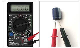
Image
 Capacitor Testing Before checking a capacitor, ensure it is discharged. If not, discharge it safely. You can check the capacitor using a digital multimeter in both resistance and continuity modes. This guide will focus on the continuity mode method. Steps: Identify the capacitor type: Determine if it is a polar or non-polar capacitor. Non-polar capacitor: Connect the multimeter probes to the capacitor's terminals. If a beep sounds, the capacitor is faulty (short circuit). No beep indicates a good capacitor. Polar capacitor: Briefly touch the probes to the terminals . You may see a brief reading, followed by a value of 1. This indicates a good capacitor. You may also reverse the probes and repeat the process for confirmation. Note: Discharging capacitors requires caution and specific methods. Always consult a professional or relevant resources for safe discharging procedures.

Resistor Testing

Image
Resistor Testing  Resistors are a common component used in electronic circuits, but when building a circuit, it is important to pay attention to whether its value is correct or faulty. You can also find its value through color coding, or some have their values marked on them. Let's learn how to find the value of any resistor and whether it is okay or faulty. Here are the steps on how to check the value of a resistor: Check the color code. Resistors are color-coded, which means that the value of the resistor is indicated by the colors of the bands on its body. The first two bands represent the first two digits of the resistor's value, the third band represents the multiplier, and the fourth band represents the tolerance. For example, a resistor with the following color bands: Brown (1) Black (0) Red (2) Gold (5%) Would have a value of 100 ohms with a tolerance of 5 %. Use a multimeter. Step 1 First, set the black probe of the multimeter to Common Mode and the red probe to R...

Introduction

 An Introduction to Components Testing Welcome to the exciting world of electronics! As you embark on your journey, understanding how to test and verify the functionality of various electronic components is crucial. These components testing forms a vital foundation for successful circuit building and troubleshooting. Why is Components Testing Important? Imagine building a complex structure with faulty bricks. The entire structure would be compromised, right? Similarly, using faulty components can lead to malfunctioning circuits, wasted time, and frustration. By testing components beforehand, you can avoid these pitfalls and ensure your circuits perform as intended. The Tools of the Trade: Just like any other profession, electronics has its own set of specialized tools. Here are some key instruments for component testing: Multimeter: This versatile tool measures voltage, current, and resistance, allowing you to check the basic health of various components like resistors, capacitors...

Digital Multimeter

Image
Digital Multimeter A digital multimeter is an electronic instrument used to measure the values of various electrical quantities, such as resistance, capacitance, and voltage. It can be used for both DC and AC. The multimeter has different sections for measuring each quantity, which can be set using the rotary knob. It also has a display to show the measured value. Two probes are provided to make contact with a component or PCB. Key Points A digital multimeter is an electronic instrument used to measure electrical quantities. It can measure resistance, capacitance, and voltage. It can be used for both DC and AC. It has different sections for measuring each quantity. It has a rotary knob to set the measurement mode. It has a display to show the measured value. It has two probes to make contact with a component or PCB.